
The Complete Guide to FCAW & GMAW Welding: Positions, Techniques & Parameters By Ultramet Welds
Discover FCAW and GMAW welding processes, weaving techniques, welding positions, and industrial weld inspection methods.
5/19/202610 min read
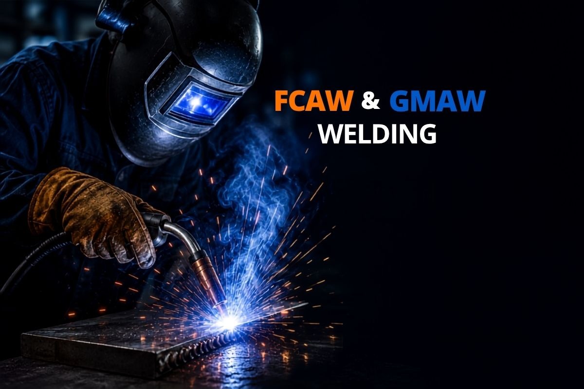
Whether you are a welding apprentice preparing for your certification, an engineer specifying a process, or a project manager evaluating suppliers, understanding the fundamentals of Flux-Cored Arc Welding (FCAW) and Gas Metal Arc Welding (GMAW) is essential. These two processes dominate modern industrial welding from structural steel fabrication to precision stainless steel components.
In this guide, Ultramet Welds covers everything you need to know: welding positions, direction of travel, electrode extension, arc length, deposition rate, weaving technique, weld length requirements, and how to identify incorrect parameters on stainless steel. We also compare FCAW and GMAW side by side so you can choose the right process for your project.
What Welding Positions Can FCAW Be Performed In?
FCAW is one of the most versatile arc welding processes available. It can be performed in all four primary welding positions:
Flat (1G/1F)
The easiest and most productive position. Gravity assists the weld pool, allowing higher deposition rates and better bead appearance.
Horizontal (2G/2F)
The electrode is held horizontally while the weld is made along a vertical surface. Gravity pulls the weld pool downward, so the welder must compensate with travel angle and travel speed.
Vertical (3G/3F)
Welding is performed on a vertical surface, either upward (vertical-up) or downward (vertical-down). Vertical-up is used for thicker materials requiring full penetration; vertical-down is faster and suited to thinner materials.
Overhead (4G/4F)
The most demanding position. The welder works with the weld pool above their head. Gravity constantly threatens to pull molten metal downward, requiring careful arc length and technique control.
The ability to weld in all positions makes FCAW ideal for large-scale structural fabrication, site welding, and repair work where repositioning the workpiece is not always possible.
Need professional FCAW welding across all positions? Ultramet Welds operates with certified welders qualified for all-position work. Contact us for a project assessment.
Direction of Travel & the Stepping Motion in Flat Position FCAW
When welding in the flat position with FCAW, the correct direction of travel is generally a drag (backhand) technique the electrode is angled back toward the completed weld, pointing away from the direction of travel. This produces deeper penetration and a more stable arc.
Direction of travel must always be evaluated in the context of the specific wire type and shielding system being used. Self-shielded FCAW wires (FCAW-S) have different travel angle requirements than gas-shielded wires (FCAW-G).
What Is the Stepping Motion and Why Does It Matter
The stepping motion also called a pause-and-step or hesitation technique involves briefly pausing the electrode at the toes of the weld bead before moving forward. In flat and horizontal positions, this technique provides two critical benefits:
It allows the weld metal to cool slightly, reducing the risk of the pool becoming too fluid, sagging, or running ahead of the arc.
It gives the slag time to float to the surface, improving bead cleanliness and reducing the risk of slag inclusions.
The stepping motion is particularly important when welding in the horizontal position, where gravity pulls the pool toward the lower plate. A welder who moves too steadily without stepping risks a convex, uneven bead with poor tie-in at the toes.
Ultramet's weld quality standards ensure correct technique is applied on every job. Learn about our quality assurance process.
Electrode Extension & Arc Length in FCAW
Electrode Extension (Contact-Tip-to-Work Distance)
Electrode extension also called Contact-Tip-to-Work Distance (CTWD) is the length of wire extending from the contact tip to the arc. Increasing electrode extension in FCAW welding increases the electrical resistance in the wire, which in turn:
Increases the preheat of the wire before it enters the arc
Reduces the actual welding current (at a given voltage setting)
Increases deposition rate slightly (more wire is melted per unit time due to resistance heating)
Can reduce penetration if taken too far
For most FCAW applications, electrode extension ranges from 19mm to 38mm (¾" to 1½"). Exceeding this range causes erratic arc behaviour, increased spatter, and loss of shielding effectiveness. Many flux cored wire manufacturers also recommend maintaining the correct CTWD to achieve stable arc performance and consistent weld quality.
Arc Length in Overhead Position
When welding in the overhead position, a long arc length is used to prevent molten metal from falling out of the weld pool. A longer arc increases arc force (the plasma jet effect), which pushes the weld pool upward against gravity and helps keep it in place. However, a very long arc also reduces penetration and can cause porosity if shielding gas coverage is compromised. The welder must strike a careful balance long enough to prevent dripping, short enough to maintain a stable, well-shielded arc.
Ultramet uses calibrated equipment and procedure-qualified welders to maintain optimal electrode extension and arc length on every project. Ask us about our FCAW capabilities.
Weaving Technique & Undercut Prevention in FCAW
In FCAW, welders use two primary bead types: stringer beads (narrow, straight passes) and weave beads (oscillating side-to-side passes). When employing a weaving technique with FCAW, a welder can eliminate problems with undercut by pausing briefly at each toe of the weld.
What Is Undercut?
Undercut is a groove or channel melted into the base metal at the toe of the weld bead that is not filled in by weld metal. It creates a stress concentration point and significantly reduces the fatigue life of the joint. Undercut is classified as a weld defect and is rejectable under most welding codes (AWS D1.1, ISO 5817, and others).
How Weaving Eliminates Undercut
When the weave motion reaches the edge of the bead, a brief pause allows sufficient weld metal to fill the toe and prevents the arc from burning into the base metal without depositing enough filler. The key parameters are:
Weave width: Generally no more than 2.5× the electrode diameter to avoid excessive heat input
Pause duration at each toe: Typically 0.5–1 second enough to fill without overheating
Travel speed: Steady and consistent through the centre of the weave
Ultramet's NDT inspection process detects undercut and all other weld discontinuities before any component leaves our facility. Learn about our inspection services.
Why FCAW Weld Lengths Should Be Substantial
A common question among welding students and junior engineers is: why should FCA welds be of substantial length? The answer lies in structural mechanics and code requirements.
Weld Length and Load Distribution
A weld transfers stress between the base metal components it joins. Short welds concentrate stress at their ends particularly at the start and stop craters creating points of potential fatigue cracking under cyclic loading. A longer weld distributes the load over a greater area, reducing peak stress at any single point.
Code Minimums
Welding codes such as AWS D1.1 (Structural Welding Code Steel) specify minimum effective weld lengths. For example, a fillet weld must have an effective length of at least four times its size, and never less than 38mm (1½"). Welds shorter than this minimum are considered to carry no load for design purposes they are not just inefficient, they are non-compliant and potentially dangerous.
Start and Stop Craters
Every weld has a start and a stop. The stop crater, if not properly filled, is the weakest point of the weld. With short welds, these defect-prone zones represent a disproportionately large share of the total weld length. Longer welds reduce this ratio significantly.
Ultramet produces structurally compliant welds that meet or exceed AWS, ISO, and client-specific requirements. Request a project quote from our structural welding team.
Wire Melting Rate vs. Deposition Rate What Is the Difference?
Wire Melting Rate
The wire melting rate is the total rate at which the electrode wire is consumed by the arc, measured in kg/hr or lb/hr. It accounts for all wire melted including any wire that becomes spatter and is lost to the atmosphere before reaching the joint.
Deposition Rate
The deposition rate is the rate at which weld metal is actually deposited into the joint. It is always lower than the wire melting rate because some molten metal is lost as spatter before it reaches the weld pool.
Deposition Efficiency
The ratio of deposition rate to wire melting rate is called deposition efficiency:
FCAW-G (gas-shielded): typically 85–95% deposition efficiency
FCAW-S (self-shielded): generally slightly lower due to higher spatter levels
GMAW (MIG) spray transfer: can achieve 93–98%
Higher deposition efficiency means less wire waste, lower consumable cost, and faster fill rates for large joints. Understanding deposition rate is critical for project cost estimation. A welding engineer who knows the required weld volume can calculate the hours needed and select the most cost-effective process and wire combination.
Ultramet optimises process selection and parameters to maximise deposition efficiency and reduce your project cost. Talk to our engineers about welding ROI.
Stainless Steel Welding Identifying Incorrect Parameters
Stainless steel is less forgiving than carbon steel when it comes to welding parameters. Incorrect parameters show up clearly as visible defects and metallurgical changes that compromise corrosion resistance and mechanical properties.
Common Signs of Incorrect Welding Parameters on Stainless Steel
Discolouration / heat tint
Excessive heat input oxidises the chromium-oxide passive layer. Light golden tint is acceptable; blue, grey, or black tinting indicates excessive heat and loss of corrosion resistance. This is perhaps the clearest and most immediate indicator of incorrect parameters on stainless steel.
Porosity
Incorrect shielding gas mixture or flow rate causes atmospheric contamination of the weld pool, resulting in gas porosity small voids trapped in the solidified weld metal.
Burn-through / melt-through
Excessive current or too-slow travel speed on thin stainless steel causes the weld pool to penetrate completely through the material.
Sensitisation
When stainless steel is held in the temperature range of 425–870°C (800–1600°F) for too long due to excessive heat input, chromium carbides precipitate at grain boundaries. This depletes the surrounding metal of corrosion-resistant chromium, a condition known as sensitisation, making the steel susceptible to intergranular corrosion in service.
Distortion
Stainless steel has a higher coefficient of thermal expansion and lower thermal conductivity than carbon steel. It distorts more readily under excessive or poorly controlled heat input.
Ultramet specialises in precision stainless steel welding for critical industrial applications. Our parameter-controlled processes preserve corrosion resistance and dimensional accuracy. Contact our stainless steel welding team.
GMAW vs. FCAW Differences, Similarities & Vertical Position Rules
Key Differences Factor
Factor
GMAW (MIG)
FCAW
Shielding
External gas only
Flux core (+ optional gas)
Wire type
Solid rod
Hollow, flux-filled tube
Spatter
Lower
Higher (especially FCAW-S)
Outdoor use
Poor (wind-sensitive)
Excellent (especially FCAW-S)
Deposition rate
Moderate
Higher at equivalent current
Slag
None
Yes — must be removed between passes
Key Similarities
Despite their differences, GMAW and FCAW share fundamental characteristics:
Both are continuous wire-fed processes, allowing longer uninterrupted weld runs compared to SMAW (stick welding)
Both use a DC power source (typically DC electrode positive / reverse polarity)
Both require similar operator skills gun angle, travel speed, and stand-off distance management
Both can be semi-automated or fully automated with the addition of a wire feeder and robotic system
Vertical Welding Position The 3/8" Rule
Both GMAW and FCAW in the vertical position follow the same travel direction principle: vertical-down travel is used for thinner materials (under 3/8" / 10mm) where heat input must be minimised to prevent burn-through. For base metals thicker than 3/8", vertical-up travel is generally required to achieve adequate fusion and penetration vertical-down at higher currents does not allow sufficient arc dwell time for the arc to properly penetrate thicker base material.
Not sure whether GMAW or FCAW is the right process for your project? Ultramet's engineers can evaluate your joint design, material, and environment and recommend the optimal process. Get in touch
Understanding the Work Angle
Two critical angles govern weld bead placement and quality in all arc welding processes: the travel angle and the work angle.
Travel Angle
The travel angle is the angle the electrode makes with the vertical plane along the direction of travel. It determines whether the weld uses a drag (backhand) or push (forehand) technique and directly influences penetration depth and bead profile.
Work Angle
The work angle is the angle between the electrode and the work surface, measured perpendicular to the direction of travel. For a standard fillet weld on a T-joint, the work angle is 45° bisecting the angle between the two plates.
This 45° work angle is derived by splitting the 90° angle formed between the vertical plate and the horizontal plate. That is the angle that is split in order to make the work angle: the right angle made by the surface of the two joined plates. Splitting it equally places the electrode and therefore the arc at the midpoint between both plates, ensuring equal heat input and fusion on both base metal surfaces.
Deviating from the correct work angle causes unequal fusion: one plate receives more heat than the other, leading to undercut on one side and poor penetration on the other.
Ultramet's certified welders are trained and regularly assessed on correct gun angles for every joint type and position. Trust our team for precision weld placement.
What Is EL8? Understanding Electrode Classifications
EL8 is an electrode classification used in flux-cored and submerged arc welding. Breaking it down:
E = Electrode
L = Low alloy (indicating alloying chemistry and flux system type)
8 = Specific classification number indicating chemical composition and usability characteristics
EL8 electrodes are low-manganese, low-alloy wires typically used in submerged arc welding (SAW) in combination with a neutral flux, rather than open-arc FCAW. They are designed for applications requiring controlled manganese content in the weld deposit such as certain pressure vessel and structural applications where manganese pick-up from the flux must be carefully managed.
Electrode classification systems are defined by standards including AWS A5.20 (FCAW carbon steel wires), AWS A5.22 (stainless FCAW wires), and AWS A5.36 (the newer unified classification). These standards specify mechanical properties, usability positions, and chemical composition. Selecting the correct electrode classification for your base metal, joint design, and service conditions is critical to achieving a code-compliant, reliable weld.
Ultramet selects consumables to match your exact specification base metal, service environment, and code requirements. Ask our team how we specify electrodes for your project.
NDT, Reliability & Weld Integrity Why Inspection Is Non-Negotiable
Even the most skilled welder working with perfectly dialled-in parameters can produce welds containing internal discontinuities invisible to the naked eye. This is why Non-Destructive Testing (NDT) is a mandatory part of any quality welding program for industrial, structural, and critical applications.
Common NDT Methods in Welding
Visual Testing (VT)
The first and most fundamental inspection. Catches surface defects such as undercut, cracks, porosity, and incorrect bead profile. Required as a minimum by virtually all welding codes.
Ultrasonic Testing (UT)
Uses high-frequency sound waves to detect internal flaws, lack of fusion, cracks, and inclusions in steel, stainless steel, and inox welds. Highly effective for thick-section structural components.
Radiographic Testing (RT)
X-ray or gamma-ray imaging reveals internal porosity, cracks, and inclusions. Provides a permanent film record and is required by many pressure vessel and pipeline codes.
Magnetic Particle Testing (MT)
For ferromagnetic materials, it detects surface and near-surface cracks using magnetic fields and iron particles. Fast and cost-effective for carbon steel welds.
Dye Penetrant Testing (PT)
Applies a penetrant liquid to reveal surface-breaking cracks and porosity. Effective on stainless steel, aluminium, and non-ferromagnetic materials
Reliability, Fatigue & Fracture
Welds in critical applications pressure vessels, offshore structures, crane beams, pipeline systems, inox food-grade equipment are subject to cyclic loading, thermal cycling, and corrosive environments. Weld discontinuities act as stress raisers that dramatically reduce fatigue life. A weld with an undetected crack-like defect can fail at stress levels far below the design load. NDT ensures that every weld delivered to your facility meets the structural reliability required by your design life and regulatory standards.
Ultramet offers comprehensive NDT services including VT, UT, RT, MT, and PT for steel, stainless steel, inox, and alloy welds. Inspection reports are provided with every project. Contact our NDT team for a reliability assessment.
Choosing the Right Welding Partner
FCAW and GMAW are powerful, efficient welding processes when executed correctly. The difference between a weld that passes inspection and one that fails in service lies in the details: correct position technique, controlled electrode extension, appropriate deposition rate, the right parameters for the material, and rigorous NDT.
At Ultramet Welds, we don't just weld, we engineer complete weld solutions. Our team brings certified procedure knowledge, calibrated equipment, and a quality system that gives our clients confidence at every stage of a project. As one of the trusted flux cored wire manufacturers and welding solution providers, Ultramet focuses on quality, consistency, and performance across industrial applications.
Whether you need FCAW structural fabrication, precision GMAW on stainless steel, or a complete welding and inspection package for a critical application, Ultramet has the expertise and infrastructure to deliver.
Ready to start your project? Contact Ultramet Welds today for a consultation and quote. Our team responds within one business day.
Registered Office
17, Chiman Bagh,
Subhash Marg
Indore (M.P) 452007
India
info@ultrametwelds.com
www.ultrametwelds.com

Plant
D4, Tejas Industrial Park,
Nemawar Road,
Indore (M.P) 452016
India

image from pngtree.com

mig welding wire manufacturer saw flux manufacturer india stainless steel welding wire welding wire suppliers co2 welding wire manufacturers wire welding with argon gas welding manufacturing companies mig welding wire mig wire supplier flux cored wire manufacturerhardfacing welding wirewelding stainless steel with flux core wireflux cored wire suppliersflux cored stainless mig wireflux cored wire manufacturer in indiaflux cored wire manufacturershardfacing welding wirehardfacing flux cored wire
Copyright ©2026 Ultramet Welds Pvt Ltd. All Rights Reserved